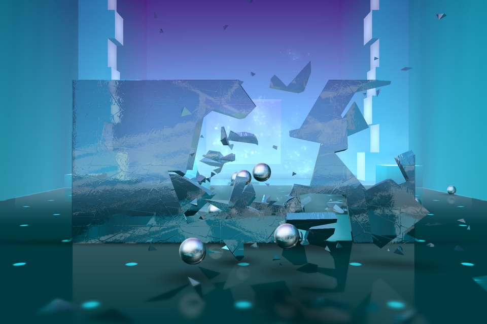
Cracking destruction
Smash Hit is a game built entirely around destruction. We knew from the beginning that destruction had to be fully procedural and also 100% reliable. Prefabricated pieces broken the same way every time simply wouldn’t be enough for the type of game we wanted to make. The clean art style and consistent materials made breakage easier, since everything that breaks is made out of the same, solid glass material.
Procedural breakage
Physically based breakage is hard. Really hard. I remember NovodeX had some kind of FEM approximation for breakage in the early days of PhysX, but it never worked well and didn’t look very convincing. I think for most game scenarios it is also completely overkill, especially for brittle fracture, like glass. I designed the breakage in Smash Hit around one rough simplification – objects always break where they get hit. This is not true in the real world, where tension builds up in the material, and objects tend to break at their weakest spot, but hey, we’re not really after accurate breakage here. What we want is breakage that feels right, and looks cool.
In Smash Hit, when a breakable object gets hit, and the exerted impulse is above a certain threshold, I carve out a small volume around the point of impact and break that up into several smaller pieces that become new dynamic objects.
It sounds simple, but looks quite convincing. However, there are a few obstacles to overcome in the implementation:
- Carving out a piece from a generic object in a robust way
- Slicing that volume
- Check for topology changes in the original object. Carving out a piece may cause it to fall apart.
Plane splitting
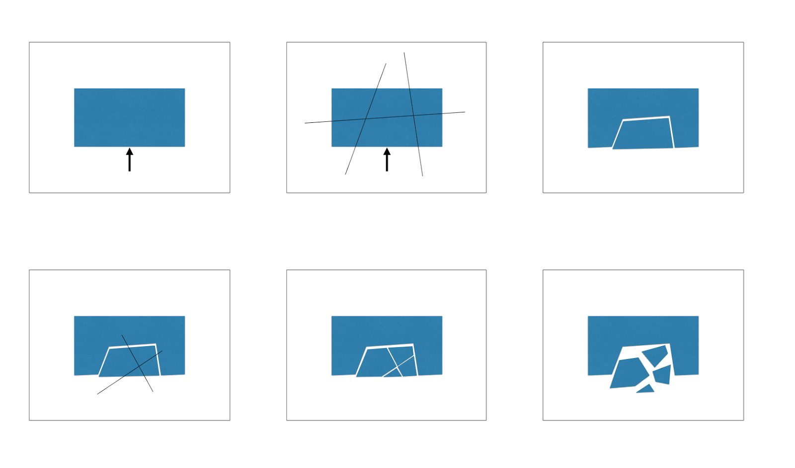
Carving out a volume from a generic mesh in a robust way is a really complex geometric problem. Furthermore, since every object in Smash Hit is physically simulated we want the resulting objects to be well-behaved in a physics-friendly format. From a physics point of view, I represent all objects as compounds of convex shapes, so the resulting broken object must also be a collection of convex shapes. Luckily there is one safe way to split up a convex object into two new objects that are also guaranteed to be convex – slicing it with a plane.
So to carve out a piece from the original object, I slice all the convex shapes with five bounding planes, slightly randomized around the point of impact. It will increase the total number of convex shapes used in the original object, but that is inevitable due to the fact we are making the object more concave. It takes a bit of bookkeeping to get the splitting code right, but as long as the plane splitting is robust, so will the overall breakage algorithm.
The carved out piece can be split up into smaller pieces using the same plane-splitting, so all we need is a really fast, reliable plane-splitting method for convex objects.
Robust splitting
The classic problem with plane-splitting is not handling degenerate cases. Say for instance one of the faces coincide with the splitting plane, so that only one edge crosses the plane due to floating point precision. That can easily result in degenerate geometry, non-closed polyhedra or even broken data structures and hard crashes. To avoid that, I start by determining a side for each vertex (above or below the plane) and then base all edge-splitting on that information, hence only split an edge if the corresponding two vertices are on opposite sides of the plane. The split point for each edge is capped to be a certain distance away from both vertices, so that the resulting two shapes are always closed, well-defined and all edges are above a certain length.
I tried quite a few data structures for doing the plane-splitting before finding one that works well in practice. The biggest hurdle was that I needed a way to track vertices through multiple splits in order to keep vertex normals consistent. It might not be visible at a first glance, but vertex normals are used extensively to make nice gradients in the glass rendering and create a certain softness to the material. Recomputing those normals after splitting an object would create a deviation in the material that is very visible to the player. In the end, the half-edge data structure turned out perfect for the job, offering both high performance and very small memory footprint. I even use 16 bit integers instead of pointers to keep the size down.
Tracking topology
After carving out a hole in the object, it needs to be checked for topology changes. Depending on the shape, it might have been split into two or more separate objects. Finding connected components in a series of inter-connected nodes is classic graph theory. What makes out a connection in this case is wether two shapes are touching face to face. The most elegant way to do this would be to track split faces between shapes and remember the connections, but it takes a lot of bookkeeping. I’m using a more pragmatic approach, where the distance between shapes are measured geometrically. I have earlier on this blog written about the GJK algorithm and how immensely useful it is for all kinds of geometric operations. In this case, we only want to know if two object are within a certain distance of each other. This can be done as a simple overlap test in configuration space, which is extremely fast.
The algorithm for finding connected components goes like this:
Assign each object a unique id
For each object A
  For each object B
    If id[A] and id[B] are different and they are touching
      Replace all id[A] and id[B] with min(id[A], id[B])
  Next
Next
After we’re done all shapes with the same id represent the same rigid body. This is obviously not a very fast general algorithm due to cubic complexity, but since the number of shapes in a rigid body is usually within a few dozen it works well in practice. The nice thing about it is the complete lack of state, which simplifies further breakage.
Simulation pipeline
A final word on breakage is the importance of getting the simulation pipeline right. With an off-the-shelf physics engine, contact impulses are typically analyzed after the simulation step to determine if something breaks. This give the impression of unbreakable objects colliding and then artificially split up afterwards. The key to natural looking breakage is to limit the contact forces of a breakable object during the simulation and break them up while preserving some of the motion. There are tricks to mix in some of the pre-break velocity on broken pieces, but I went all in and actually do multiple solves during breakage, so a simulation step typically involves running the following steps:
- General collision detection
- Run solver with capped impulses on breakable objects
- Check if some contacts reached the cap and in that case break objects
- Collision detection for new objects
- Run the solver again on affected contacts with capped impulses
- Repeat from 3
- Integrate
This means that objects are created and broken several times during a simulation step before proceeding to integration. I have capped the number of solves per simulation step to three in order to limit performance impact.
This is the first game where I’m giving my low level physics engine a proper work-out. It has been in development on and off for almost four years so it’s great to finally see it in action. Good destruction ties very deeply into the simulation pipeline, so it’s not ideal to plaster it on top of an existing physics engine.